A
rectifier is an electrical device that converts alternating current (AC), which periodically reverses direction, to direct current (DC), which is in only one direction, a process known as
rectification. Rectifiers have many uses including as components of power supplies and as detectors of radio signals. Rectifiers may be made of solid state diodes, silicon-controlled rectifiers, vacuum tube diodes, mercury arc valves, and other components.
A device which performs the opposite function (converting DC to AC) is known as an inverter...
Now we come to the most popular application of the diode:
rectification. Simply defined, rectification is the conversion of alternating current (AC) to direct current (DC). This involves a device that only allows one-way flow of electrons. As we have seen, this is exactly what a semiconductor diode does. The simplest kind of rectifier circuit is the
half-wave rectifier. It only allows one half of an AC waveform to pass through to the load. (Figure below)
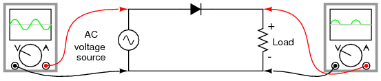 Half-wave rectifier circuit.
For most power applications, half-wave rectification is insufficient for the task. The harmonic content of the rectifier's output waveform is very large and consequently difficult to filter. Furthermore, the AC power source only supplies power to the load one half every full cycle, meaning that half of its capacity is unused. Half-wave rectification is, however, a very simple way to reduce power to a resistive load. Some two-position lamp dimmer switches apply full AC power to the lamp filament for “full” brightness and then half-wave rectify it for a lesser light output. (Figure below)
 Half-wave rectifier application: Two level lamp dimmer.
In the “Dim” switch position, the incandescent lamp receives approximately one-half the power it would normally receive operating on full-wave AC. Because the half-wave rectified power pulses far more rapidly than the filament has time to heat up and cool down, the lamp does not blink. Instead, its filament merely operates at a lesser temperature than normal, providing less light output. This principle of “pulsing” power rapidly to a slow-responding load device to control the electrical power sent to it is common in the world of industrial electronics. Since the controlling device (the diode, in this case) is either fully conducting or fully nonconducting at any given time, it dissipates little heat energy while controlling load power, making this method of power control very energy-efficient. This circuit is perhaps the crudest possible method of pulsing power to a load, but it suffices as a proof-of-concept application.
If we need to rectify AC power to obtain the full use of
both half-cycles of the sine wave, a different rectifier circuit configuration must be used. Such a circuit is called a
full-wave rectifier. One kind of full-wave rectifier, called the
center-tap design, uses a transformer with a center-tapped secondary winding and two diodes, as in Figure below.
 Full-wave rectifier, center-tapped design.
This circuit's operation is easily understood one half-cycle at a time. Consider the first half-cycle, when the source voltage polarity is positive (+) on top and negative (-) on bottom. At this time, only the top diode is conducting; the bottom diode is blocking current, and the load “sees” the first half of the sine wave, positive on top and negative on bottom. Only the top half of the transformer's secondary winding carries current during this half-cycle as in Figure below.
 Full-wave center-tap rectifier: Top half of secondary winding conducts during positive half-cycle of input, delivering positive half-cycle to load..
During the next half-cycle, the AC polarity reverses. Now, the other diode and the other half of the transformer's secondary winding carry current while the portions of the circuit formerly carrying current during the last half-cycle sit idle. The load still “sees” half of a sine wave, of the same polarity as before: positive on top and negative on bottom. (Figure below)
 Full-wave center-tap rectifier: During negative input half-cycle, bottom half of secondary winding conducts, delivering a positive half-cycle to the load.
One disadvantage of this full-wave rectifier design is the necessity of a transformer with a center-tapped secondary winding. If the circuit in question is one of high power, the size and expense of a suitable transformer is significant. Consequently, the center-tap rectifier design is only seen in low-power applications.
The full-wave center-tapped rectifier polarity at the load may be reversed by changing the direction of the diodes. Furthermore, the reversed diodes can be paralleled with an existing positive-output rectifier. The result is dual-polarity full-wave center-tapped rectifier in Figure below. Note that the connectivity of the diodes themselves is the same configuration as a bridge.
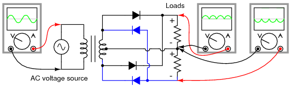 Dual polarity full-wave center tap rectifier
Another, more popular full-wave rectifier design exists, and it is built around a four-diode bridge configuration. For obvious reasons, this design is called a
full-wave bridge. (Figure below)
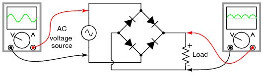 Full-wave bridge rectifier.
Current directions for the full-wave bridge rectifier circuit are as shown in Figure below for positive half-cycle and Figure below for negative half-cycles of the AC source waveform. Note that regardless of the polarity of the input, the current flows in the same direction through the load. That is, the negative half-cycle of source is a positive half-cycle at the load. The current flow is through two diodes in series for both polarities. Thus, two diode drops of the source voltage are lost (0.7·2=1.4 V for Si) in the diodes. This is a disadvantage compared with a full-wave center-tap design. This disadvantage is only a problem in very low voltage power supplies.
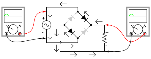 Full-wave bridge rectifier: Electron flow for positive half-cycles.
 Full-wave bridge rectifier: Electron flow for negative half=cycles.
Remembering the proper layout of diodes in a full-wave bridge rectifier circuit can often be frustrating to the new student of electronics. I've found that an alternative representation of this circuit is easier both to remember and to comprehend. It's the exact same circuit, except all diodes are drawn in a horizontal attitude, all “pointing” the same direction. (Figure below}
 Alternative layout style for Full-wave bridge rectifier.
One advantage of remembering this layout for a bridge rectifier circuit is that it expands easily into a polyphase version in Figure below.
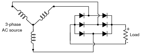 Three-phase full-wave bridge rectifier circuit.
Each three-phase line connects between a pair of diodes: one to route power to the positive (+) side of the load, and the other to route power to the negative (-) side of the load. Polyphase systems with more than three phases are easily accommodated into a bridge rectifier scheme. Take for instance the six-phase bridge rectifier circuit in Figure below.
 Six-phase full-wave bridge rectifier circuit.
When polyphase AC is rectified, the phase-shifted pulses overlap each other to produce a DC output that is much “smoother” (has less AC content) than that produced by the rectification of single-phase AC. This is a decided advantage in high-power rectifier circuits, where the sheer physical size of filtering components would be prohibitive but low-noise DC power must be obtained. The diagram in Figure below shows the full-wave rectification of three-phase AC.
 Three-phase AC and 3-phase full-wave rectifier output.
In any case of rectification -- single-phase or polyphase -- the amount of AC voltage mixed with the rectifier's DC output is called
ripple voltage. In most cases, since “pure” DC is the desired goal, ripple voltage is undesirable. If the power levels are not too great, filtering networks may be employed to reduce the amount of ripple in the output voltage.
Sometimes, the method of rectification is referred to by counting the number of DC “pulses” output for every 360
o of electrical “rotation.” A single-phase, half-wave rectifier circuit, then, would be called a
1-pulse rectifier, because it produces a single pulse during the time of one complete cycle (360
o) of the AC waveform. A single-phase, full-wave rectifier (regardless of design, center-tap or bridge) would be called a
2-pulse rectifier, because it outputs two pulses of DC during one AC cycle's worth of time. A three-phase full-wave rectifier would be called a
6-pulse unit.
Modern electrical engineering convention further describes the function of a rectifier circuit by using a three-field notation of
phases,
ways, and number of
pulses. A single-phase, half-wave rectifier circuit is given the somewhat cryptic designation of 1Ph1W1P (1 phase, 1 way, 1 pulse), meaning that the AC supply voltage is single-phase, that current on each phase of the AC supply lines moves in only one direction (way), and that there is a single pulse of DC produced for every 360
o of electrical rotation. A single-phase, full-wave, center-tap rectifier circuit would be designated as 1Ph1W2P in this notational system: 1 phase, 1 way or direction of current in each winding half, and 2 pulses or output voltage per cycle. A single-phase, full-wave, bridge rectifier would be designated as 1Ph2W2P: the same as for the center-tap design, except current can go
both ways through the AC lines instead of just one way. The three-phase bridge rectifier circuit shown earlier would be called a 3Ph2W6P rectifier.
Is it possible to obtain more pulses than twice the number of phases in a rectifier circuit? The answer to this question is yes: especially in polyphase circuits. Through the creative use of transformers, sets of full-wave
rectifiers may be paralleled in such a way that more than six pulses of DC are produced for three phases of AC. A 30
o phase shift is introduced from primary to secondary of a three-phase transformer when the winding configurations are not of the same type. In other words, a transformer connected either Y-Δ or Δ-Y will exhibit this 30
o phase shift, while a transformer connected Y-Y or Δ-Δ will not. This phenomenon may be exploited by having one transformer connected Y-Y feed a bridge rectifier, and have another transformer connected Y-Δ feed a second bridge rectifier, then parallel the DC outputs of both
rectifiers. (Figure below Since the ripple voltage waveforms of the two
rectifiers' outputs are phase-shifted 30
o from one another, their superposition results in less ripple than either rectifier output considered separately: 12 pulses per 360
o instead of just six:
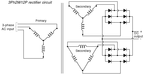 Polyphase rectifier circuit: 3-phase 2-way 12-pulse (3Ph2W12P)
- REVIEW:
- Rectification is the conversion of alternating current (AC) to direct current (DC).
- A half-wave rectifier is a circuit that allows only one half-cycle of the AC voltage waveform to be applied to the load, resulting in one non-alternating polarity across it. The resulting DC delivered to the load “pulsates” significantly.
- A full-wave rectifier is a circuit that converts both half-cycles of the AC voltage waveform to an unbroken series of voltage pulses of the same polarity. The resulting DC delivered to the load doesn't “pulsate” as much.
- Polyphase alternating current, when rectified, gives a much “smoother” DC waveform (less ripple voltage) than rectified single-phase AC.

 Transistors amplify current, for example they can be used to amplify the small output current from a logic IC so that it can operate a lamp, relay or other high current device. In many circuits a resistor is used to convert the changing current to a changing voltage, so the transistor is being used to amplify voltage.A transistor may be used as a switch (either fully on with maximum current, or fully off with no current) and as an amplifier(always partly on).


 LEDs must be connected the correct way round, the diagram may be labelled a or + for anode and k or - for cathode (yes, it really is k, not c, for cathode!). The cathode is the short lead and there may be a slight flat on the body of round LEDs. If you can see inside the LED the cathode is the larger electrode (but this is not an official identification method). LEDs can be damaged by heat when soldering, but the risk is small unless you are very slow. No special precautions are needed for soldering most LEDs.

 LEDs are available in red, orange, amber, yellow, green, blue and white. Blue and white LEDs are much more expensive than the other colours. The colour of an LED is determined by the semiconductor material, not by the colouring of the 'package' (the plastic body). LEDs of all colours are available in uncoloured packages which may be diffused (milky) or clear (often described as 'water clear'). The coloured packages are also available as diffused (the standard type) or transparent.


